Leírás
-
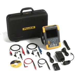
Measurement Function DC voltage (V dc) Maximum voltage with 10:1 or 100:1 probe 1000 V Maximum resolution with 10:1 or 100:1 probe 1 mV Full scale reading 999 counts Accuracy at 4 s to 10 us/div ±(3 % + 6 counts) AC voltage (V ac) Maximum voltage with 10:1 or 100:1 probe 1000 V Maximum resolution with 10:1 or 100:1 probe 1 mV Full scale reading 999 counts 50 Hz ±(3 % + 10 counts) – 0.6 % 60 Hz ±(3 % + 10 counts) – 0.4 % 60 Hz to 20 kHz ±(4 % + 15 counts) 20 kHz to 1 MHz ±(6 % + 20 counts) 1 MHz to 25 MHz ±(10 % + 20 counts) True-rms voltage (V ac+dc) Maximum voltage with 10:1 or 100:1 probe 1000 V Maximum resolution with 10:1 or 100:1 probe 1 mV Full scale reading 1100 counts DC to 60 Hz ±(3 % + 10 counts) 60 Hz to 20 kHz ±(4 % + 15 counts) 20 kHz to 1 MHz ±(6 % + 20 counts) 1 MHz to 25 MHz ±(10 % + 20 counts) PWM voltage (V pwm) Purpose To measure on pulse width modulated signals, like motor drive inverter outputs Principle Readings show the effective voltage based on the average value of samples over a whole number of periods of the fundamental frequency Accuracy As Vac+dc for sinewave signals Peak voltage (V peak) Modes Max peak, min peak, or pk-to-pk Maximum voltage with 10:1 or 100:1 probe 1000 V Maximum resolution with 10:1 or 100:1 probe 10 mV Accuracy Max peak, min peak ±0.2 division Pk-to-pk ±0.4 division Full scale reading 800 counts General Specification Current (AMP) with current clamp Ranges Same as V ac, Vac+dc or V peak Scale Factors 0.1 mV/A, 1 mV/A, 10 mV/A, 20 mV/A, 50mV/A, 100 mV/A, 200 mV/A, 400 mV/A Accuracy Same as Vac, Vac+dc or V peak (add current clamp accuracy) Frequency (Hz) Range 1.000 Hz to 500 MHz Full scale reading 999 counts Accuracy ±(0.5 % + 2 counts) Voltage/Herz ratio (V/Hz) Purpose To show the measured V PWM value (see V PWM) divided by the fundamental frequency on variable ac motor speed drives Accuracy % Vrms + % Hz Voltage unbalance drive input Purpose To show the highest percentage difference of one of the phase vs average of the 3 true-rms voltages Accuracy Indicative percentage based on Vac+dc values Voltage unbalance drive output and motor input Purpose To show the highest percentage difference of one of the phase vs average of the 3 PWM voltages Accuracy Indicative percentage based on V PWM values Current unbalance drive input Purpose To show the highest percentage difference of one of the phase vs average of the 3 AC current values Accuracy Indicative percentage based on Aac+dc values Current unbalance drive output and motor input Purpose To show the highest percentage difference of one of the phase vs average of the 3 AC current values Accuracy Indicative percentage based on A ac values Rise and fall time Readings Voltage difference (dV), time difference (dt), voltage vs time difference (dV/dt), overshoot Accuracy As oscilloscope accuracy Harmonics and spectrum Harmonics DC to 51st Spectrum ranges 1…9 kHz, 9-150 kHz (20 MHz filter on), up to 500 MHz (voltage modulation) Shaft voltage Events / second Indicative percentage based on rise and fall time (Impulse discharges) measurements Report data capture Number of screens Typical 50 screens can be saved in reports (depends on compression ratio) Transfer to PC Using 2 GB USB stick or mini-USB to USB cable and FlukeView™ 2 for ScopeMeter™ test tool Probe settings Voltage probe 1:1, 10:1, 100:1, 1000:1, 20:1, 200:1 Current clamp 0.1 mV/A, 1 mV/A, 10 mV/A, 20 mV/A, 50 mV/A, 100 mV/A, 200 mV/A, 400 mV/A Shaft voltage probe 1:1, 10:1, 100:1
 Letölthető műszaki specifikáció